3.1. Overview
In PostgreSQL, a single backend process typically handles all queries issued by a connected client.
The backend consists of five primary subsystems:
- Parser: Creates a parse tree from a plain-text SQL statement.
- Analyzer/Analyser: Performs semantic analysis of the parse tree and creates a query tree.
- Rewriter: Transforms the query tree according to rules stored in the rule system, if any such rules exist.
- Planner: Creates the most efficient plan tree from the query tree.
- Executor: Executes the query by accessing tables and indexes in the order specified by the plan tree.
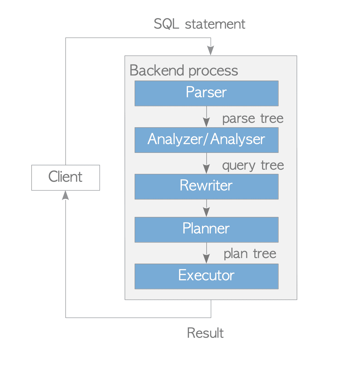
Figure 3.1. Query Processing.
This section provides an overview of these subsystems. Because the planner and the executor are highly complex, their functions are explained in detail in the subsequent sections.
3.1.1. Parser
The parser creates a parse tree from a plain-text SQL statement that can be processed by subsequent subsystems. Below is a specific example illustrating this process.
Consider the following query:
testdb=# SELECT id, data FROM tbl_a WHERE id < 300 ORDER BY data;A parse tree is a data structure whose root is the SelectStmt structure, defined in parsenodes.h.
Figure 3.2(b) illustrates the parse tree of the query shown in Figure 3.2(a).
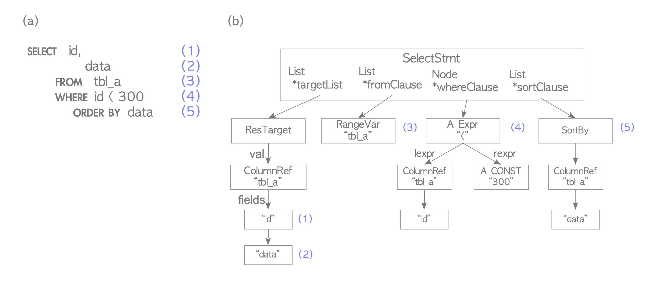
Figure 3.2. An example of a parse tree.
The elements of the SELECT query are mapped to corresponding nodes in the parse tree, indicated by the matching numbers in Figure 3.2. For example:
- (1) is an item in the target list, representing the ‘id’ column.
- (4) represents the WHERE clause.
The parser validates only the syntax of the input query. Consequently, it returns an error only if the query contains a syntax violation.
The parser does not perform semantic checks; for example, it will not return an error even if the query references a non-existent table. All semantic validations are handled by the analyzer/analyser.
3.1.2. Analyzer/Analyser
The analyzer/analyser performs a semantic analysis of the parse tree created by the parser and produces a query tree.
The root of a query tree is the Query structure, defined in parsenodes.h.
This structure contains metadata for the query — such as the command type (SELECT, INSERT, etc.) — and several leaves.
Each leaf constitutes a list or a tree that holds data for a specific clause.
Figure 3.3 illustrates the query tree for the query shown in Figure 3.2(a) from the previous subsection.
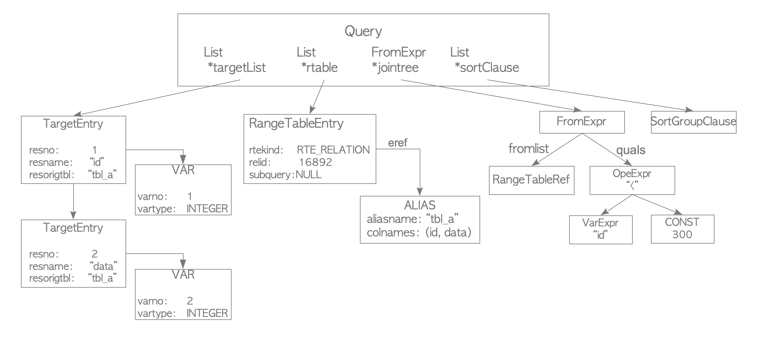
Figure 3.3. The Query Tree of the SELECT query in Figure 3.2.
The query tree shown above is summarized as follows:
- targetlist: A list of columns that form the result of the query. In this example, the list contains two columns: ‘id’ and ‘data’. If the input query uses an asterisk (’*’), the analyzer/analyser explicitly expands it into all available columns.
- range table: A list of relations (tables) used in the query. In this example, the range table holds metadata for ’tbl_a’, such as its OID and name.
- jointree: A structure that stores the FROM and WHERE clauses.
- sortClause: A list of
SortGroupClausestructures.
The official documentation briefly describes the details of query trees.
3.1.3. Rewriter
The rewriter is the subsystem based on the rule system. It transforms a query tree according to the rules stored in the pg_rules system catalog, when applicable.
Although the rewriter and the rule system are powerful features, this section focuses on how they implement Views, using a specific example.
3.1.3.1. Views
When a view is defined with the CREATE VIEW command, a corresponding rule is automatically created and stored in the system catalog.
Assume that the following view has been defined and its corresponding rule is stored in the pg_rules system catalog:
sampledb=# CREATE VIEW employees_list
sampledb-#      AS SELECT e.id, e.name, d.name AS department
sampledb-#            FROM employees AS e, departments AS d WHERE e.department_id = d.id;
When the query shown below is issued, the parser creates a parse tree as illustrated in Figure 3.4(a).
sampledb=# SELECT * FROM employees_list;At this stage, the rewriter transforms the range table node into a subquery parse tree based on the view definition stored in pg_rules system catalog.
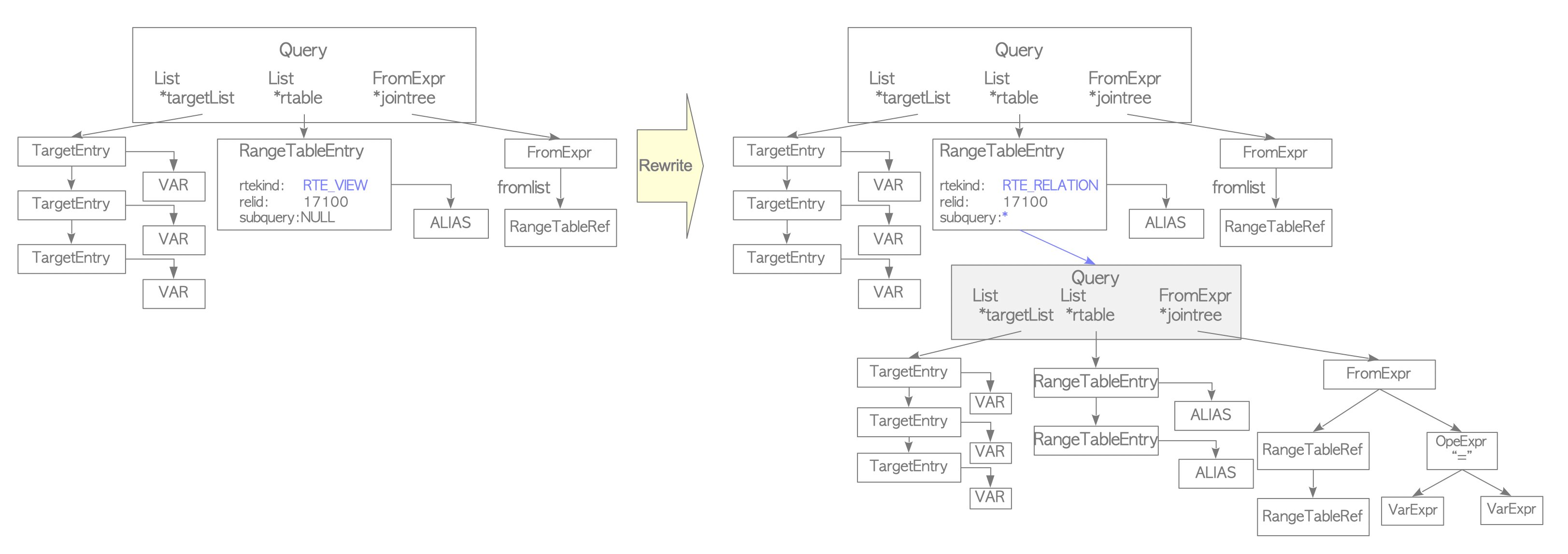
Figure 3.4. An example of the rewriter stage.
Because PostgreSQL implements views using this mechanism, they were not updatable prior to version 9.2. Although updatable views were introduced in version 9.3, several limitations remain. For further details, refer to the official documentation.
3.1.4. Planner and Executor
The planner receives a query tree from the rewriter and creates a (query) plan tree optimized for efficient execution by the executor.
PostgreSQL’s planner is based on pure cost-based optimization; it does not support rule-based optimization or hints. As the most complex subsystem in PostgreSQL, a detailed overview of the planner is provided in the subsequent sections of this chapter.
PostgreSQL does not support planner hints in SQL, and there are no plans to support them in the future.
To use hints in queries, consider installing the pg_hint_plan extension.
Similar to other RDBMSs, the EXPLAIN command in PostgreSQL displays the plan tree. A specific example is shown below:
|
|
This output represents the plan tree illustrated in Figure 3.5.
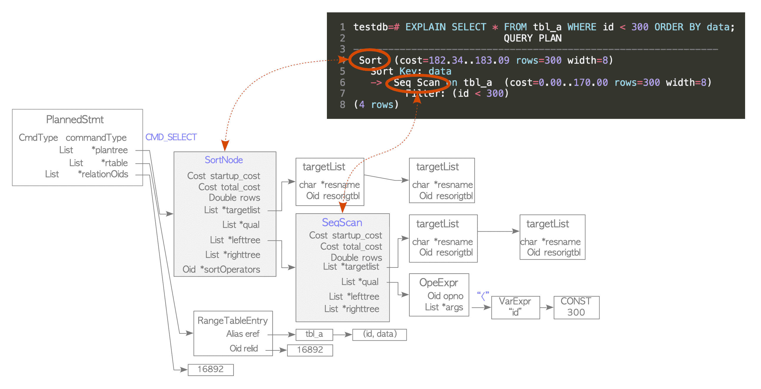
Figure 3.5. A simple plan tree and the relationship between the plan tree and the result of the EXPLAIN command.
A plan tree is composed of elements called plan nodes, which are linked to the plantree list of the PlannedStmt structure.
These elements are defined in plannodes.h.
For more details, refer to Section 3.3.3 and Section 3.5.4.2.
Each plan node contains the metadata required by the executor. In a single-table query, data flows through the plan tree from the leaves (bottom) up to the root. This execution follows the Volcano Model (also known as the Iterator Model), where tuples are processed and passed upward one at a time.
For example, the plan tree in Figure 3.5. consists of a Sort node and a Sequential Scan node. Consequently, the executor performs a sequential scan of the table tbl_a and then sorts the retrieved result1.
The executor interacts with tables and indexes via the buffer manager, as described in Chapter 8. During processing, the executor utilizes allocated memory areas such as temp_buffers and work_mem, and creates temporary files if the data exceeds the available memory. See Figure 3.6.
Furthermore, when accessing tuples, PostgreSQL employs a concurrency control mechanism to maintain the atomicity and isolation of active transactions. This mechanism is detailed in Chapter 5.
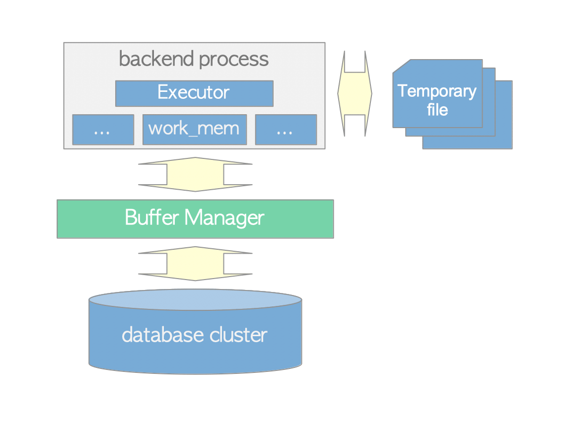
Figure 3.6. The relationship among the executor, buffer manager and temporary files.
-
From the perspective of control flow rather than data flow, the executor processes the plan tree from the top down. For instance, in this example, the executor invokes the Sort node, which in turn triggers the Sequential Scan node. ↩︎